
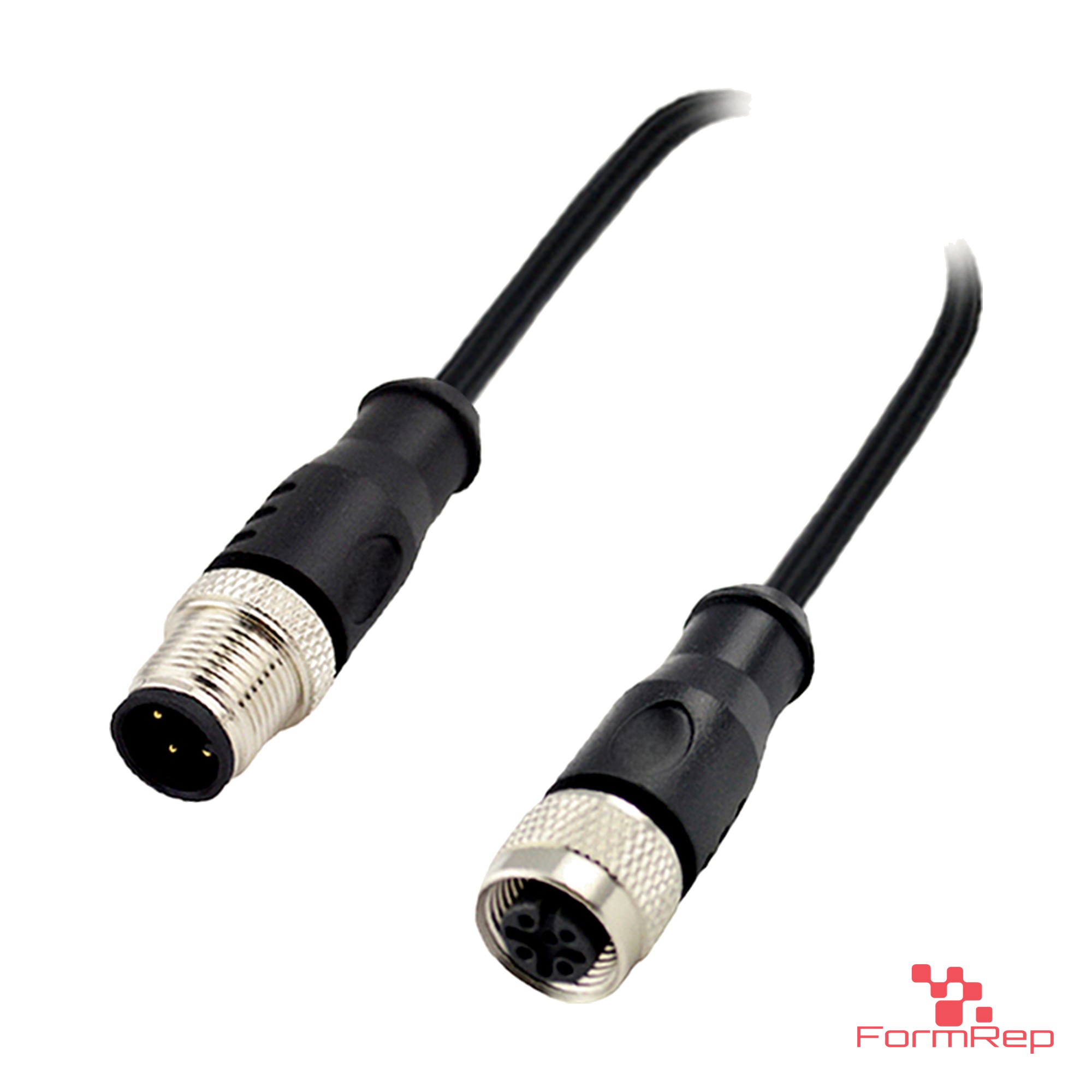
Short answer The coding letter is the key shape on the face of an M12 connector. It decides what the connector is for and stops the wrong two from mating. A-coding is for sensors and low-power DC, B for PROFIBUS, C for AC sensors, D and X for Ethernet, S and K for AC power, T and L for DC power, and Y for power and data in one connector. Match the coding first, then the pin count, then male or female.
Why M12 connectors are coded
Every M12 connector has the same 12 mm threaded coupling, so a 24 V sensor cable and a 400 V motor cable could look alike from across the panel. The coding is a key (a notch or rib) molded into the connector face. Two connectors only mate when their coding matches. That keeps a sensor cable out of a power port and an Ethernet cable out of a fieldbus port.
Look straight at the face of the connector. The position of the key and the layout of the pins tell you the coding. Most connectors also have the letter printed on the body or listed on the data sheet.
M12 coding chart
| Coding | What it’s for | Typical pins | Typical limits in the standard |
|---|---|---|---|
| A | Sensors, actuators, IO-Link, DeviceNet and CANopen, low-power DC | 3, 4, 5, 8, 12, 17 | Up to about 4 A and 250 V on 3–5 pins; lower as pin count rises |
| B | PROFIBUS DP fieldbus data | 4, 5 | Data; about 4 A |
| C | AC sensors and actuators | 3, 4, 5, 6 | Up to about 250 V AC |
| D | 100 Mbit Ethernet: PROFINET, EtherNet/IP, EtherCAT | 4 | Cat 5e data |
| X | Gigabit Ethernet, up to 10 Gbit | 8 | Cat 6A data, shielded |
| S | AC power for motors, drives and heaters | 3 + PE | Up to about 630 V AC, 12 A |
| K | AC power with one more conductor (drives) | 4 + PE | Up to about 630 V AC, 12 A |
| T | DC power for I/O blocks and devices | 4 | Up to about 63 V DC, 12 A |
| L | Higher-current DC power, PROFINET power | 4 + FE | Up to about 63 V DC, 16 A |
| Y | Hybrid: power and Ethernet in one connector | 8 (4 power, 4 data) | 100 Mbit data plus DC power |
The limits above are the typical maximums for each coding. A given cable or connector can be rated lower depending on wire size, jacket and temperature, so check the rating on that part’s data sheet.
How to pick the right cable in four steps
- Coding. Read it off the device port or its manual. If the port is A-coded, every cable on it is A-coded.
- Pin count. Match the port. A sensor that only uses 3 wires still needs the cable to fit its 4- or 5-pin port layout.
- Male or female. Male has pins, female has sockets. Device ports on sensors are usually male, so the cable end that plugs into them is female.
- Straight or right-angle, and length. Right-angle ends save space where the port faces a wall or a moving part. Measure the run, then add a little slack for strain relief.
Signal, data and power: the three groups
- Signal (A, B, C): the everyday sensor and fieldbus connectors. A-coding is by far the most common one on a machine.
- Data (D, X): Industrial Ethernet. D-coding is the 4-wire 100 Mbit version. X-coding is the 8-wire version for gigabit and faster, with shielding between pairs.
- Power (S, K, T, L): S and K carry AC, T and L carry DC. These have heavier contacts and should never be swapped for a signal connector to save money.
- Hybrid (Y): one connector carries both power and Ethernet, which cuts the number of cables to a device in half.
Mistakes we see
- Ordering by pin count alone and getting the wrong coding. A 4-pin A-coded and a 4-pin D-coded cable will not mate.
- Running Ethernet over a standard A-coded sensor cable. It may work on the bench and drop packets on the machine. Use D- or X-coded cable built for data.
- Using an A-coded connector for a power feed because it fits. Power codings exist because A-coded contacts are not made for that current.
- Mixing up male and female when ordering extensions. An extension is male on one end and female on the other.
- Leaving unused ports open. Cap them with a protective cap.
Shop M12 by coding
- A-coded: extension cables, single-ended cordsets, panel-mount receptacles, field-attachable connectors
- B-coded: extension cables, panel-mount receptacles
- C-coded: extension cables, panel-mount receptacles
- D-coded: extension cables, shielded field-attachable connectors
- X-coded: extension cables, panel-mount receptacles
- S-coded: extension cables, panel-mount receptacles
- K-coded: extension cables, panel-mount receptacles
- T-coded: extension cables, panel-mount receptacles
- L-coded: extension cables, panel-mount receptacles
- Y-coded: extension cables, panel-mount receptacles
Every cable comes in straight and right-angle versions, single-ended or double-ended, in several lengths. Browse them all under M12 Cables and M12 Connectors. Smaller ports use M8 and M5 cables; mobile equipment with DT-style ports can use our DT-to-M12 adapter cables.
Common questions
Can I tell the coding without a data sheet? Usually. Compare the connector face to the key positions in a coding drawing, and check the body for a printed letter. If you can’t tell, send us a photo of the face and we’ll identify it.
Is A-coded the same as “standard” M12? In practice, yes. When a sensor catalog just says “M12,” it almost always means A-coded.
Do M8 connectors use codings too? Yes, but fewer. M8 is mostly A-coded for sensors, with a D-coded version for Ethernet.
Can you build a cable that isn’t in the catalog? Yes. Odd lengths, mixed ends (for example M12 to DT-style or open leads) and made-to-fit harnesses are what we do. Send a sketch or a part number for a quote.
Shop parts Part cross-reference Request a quote
PROFIBUS, PROFINET, EtherNet/IP, EtherCAT, DeviceNet, CANopen and IO-Link are trademarks of their owners, used here for identification only.